How we optimized Cascaded Shadow Mapping

Breakdown
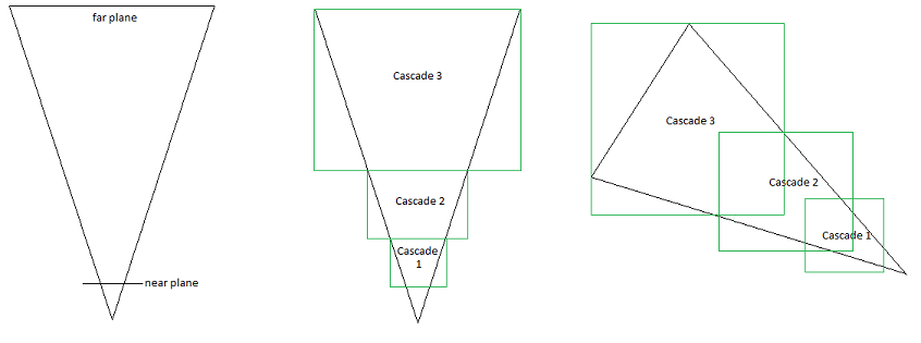
Cascaded Shadow Mapping (CSM) is a technique for rendering dynamic, high-quality shadows in expansive 3D environments. By partitioning the camera’s view frustum into multiple depth-based regions ("cascades"), CSM allocates each cascade to represent shadows at progressively farther distances from the viewer. In our implementation, we maintain uniform texture resolution across all cascades, a deliberate design choice that balances performance and visual fidelity. While each cascade’s shadow map occupies the same pixel dimensions, the world-space coverage of distant cascades increases exponentially with depth. This creates a natural gradient of shadow detail: closer cascades benefit from higher texel density for sharp, precise shadows, while distant cascades trade spatial resolution for broader coverage, aligning with the perceptual need for reduced detail at far depths. This unified resolution strategy minimizes texture memory fragmentation and computational overhead, ensuring efficiency without compromising shadow quality in typical viewing scenarios.

Figure 1
Key Concepts of Cascaded Shadow Mapping
- Frustum Partitioning: The camera’s view frustum is subdivided into four depth-based regions, as illustrated in Figure 1. Each cascade corresponds to a progressively distant segment of the scene, ensuring tighter shadow detail near the viewer and broader coverage for distant areas. Despite using identical texture resolutions for all cascades, the exponential growth in world-space coverage of farther cascades inherently reduces shadow map texel density. This mirrors perceptual priorities—high precision for foreground objects and coarser, performance-friendly approximations for distant geometry.
- Uniform Resolution Strategy: Contrary to intuition, we retain uniform shadow map resolutions across all cascades. This approach simplifies GPU resource allocation (avoiding texture atlas fragmentation) and directly enables Vulkan’s
VK_KHR_multiviewfor concurrent multi-cascade rendering in a single pass. Distant cascades naturally exhibit lower effective spatial resolution due to their expanded scene coverage—a deliberate trade-off that aligns with the viewer’s reduced sensitivity to far-depth shadow detail. By standardizing resolutions, we eliminate costly runtime adjustments while maintaining compatibility with instanced rendering pipelines. - Depth Biasing & Artifacts Management: Uniform cascade resolutions amplify artifacts like shadow acne and Peter-panning, as depth precision requirements vary across cascades. To mitigate this, we apply per-cascade slope-scaled biasing, dynamically adjusting bias values based on each cascade’s depth range and surface angles. This fine-tuning compensates for the coarser effective resolution of distant cascades while preserving foreground detail, ensuring artifact-free shadows without GPU stalls. The strategy integrates seamlessly with Vulkan’s descriptor sets, enabling efficient bias updates during render pass setup.
Our Engine’s Approach and Optimizations
In our engine, we've pushed the boundaries of CSM by integrating several optimizations to reduce draw calls and boost performance:
- Instanced Rendering: To minimize draw call overhead, we implement instanced rendering, a technique that enables the GPU to render multiple instances of the same geometry through a single draw call. This optimization dramatically reduces CPU-GPU communication costs while maximizing resource efficiency, particularly when handling the repeated geometry patterns inherent to cascaded shadow maps. By applying this approach to shadow cascade generation, we maintain high rendering performance even as the number of cascades scales.
- Vulkan Multi-Layer Rendering with VkRenderPassMultiview: For concurrent cascade processing, we harness Vulkan’s VK_KHR_multiview extension to render all shadow cascades within a single, unified render pass. By mapping each cascade to a dedicated layer, this technique eliminates redundant pass setup and minimizes CPU-GPU synchronization barriers inherent to multi-pass architectures. The result is a tightly optimized workflow that leverages GPU parallelism while maintaining the spatial precision required for cascaded shadow map generation.
This detailed breakdown lays a solid foundation for understanding cascaded shadow mapping and our unique optimization strategy. By using a uniform resolution across cascades, our engine effectively balances performance and quality, as the increased coverage in distant cascades naturally results in lower spatial resolution where high detail is less critical.
Performance Impact
By combining instanced rendering with Vulkan’s VK_KHR_multiview, we collapse what would traditionally require four separate render passes and four draw calls into a single pass and one instanced draw call. This yields:
- 75% Fewer Draw Calls: Eliminating redundant command buffer submissions for each cascade.
- 4x Reduced Synchronization: Multi-layer rendering avoids inter-pass barriers (e.g.,
VkPipelineStageFlagstransitions between passes).
These optimizations are particularly impactful in CPU-bound scenarios, where driver overhead and command buffer preparation dominate frame time.
Vulkan Setup Guide
1. Instanced Rendering Pipeline
Core Data Structures
// Groups draw calls by mesh/material/submesh to minimize state changes
struct MeshKey {
   AssetHandle MeshHandle;
   AssetHandle MaterialHandle;
   u32 SubmeshIndex;

   // Sorting operator for batching efficiency
   bool operator<(const MeshKey& other) const
   {
       if (MeshHandle < other.MeshHandle)
           return true;

       if ((MeshHandle == other.MeshHandle) && (SubmeshIndex < other.SubmeshIndex))
           return true;

       return (MeshHandle == other.MeshHandle) && (SubmeshIndex == other.SubmeshIndex) && (MaterialHandle <    other.MaterialHandle);
   }
};

// Stores per-instance transform matrices in GPU-friendly format
struct InstancedTransformVertexData {
   glm::vec4 MRow[3]; // Column-major 3x4 affine transform (optimized for vec4 alignment)
};
Transform Management
// CPU-side transform aggregation
std::map<MeshKey, TransformMapData> m_MeshTransformMap;

void SceneRenderer::SubmitMesh(Ref<Mesh>& mesh, u32 submeshIndex, const glm::mat4& transform) {
   // Decompose matrix into shader-friendly vec4 rows
   InstancedTransformVertexData transformed;
   transformed.MRow[0] = { transform[0][0], transform[1][0], transform[2][0], transform[3][0] };
   transformed.MRow[1] = { transform[0][1], transform[1][1], transform[2][1], transform[3][1] };
   transformed.MRow[2] = { transform[0][2], transform[1][2], transform[2][2], transform[3][2] };

   m_MeshTransformMap[meshKey].Transforms.push_back(transformed);
   m_DrawList[meshKey].InstanceCount++;
}
GPU Buffer Upload
// Batch upload transforms to dedicated vertex buffer
m_SubmeshTransformBuffer->SetData(
   m_TransformVertexData.data(),
   offset * sizeof(InstancedTransformVertexData), // Dynamic offset
   sizeof(InstancedTransformVertexData)          // Stride
);
Vulkan Vertex Binding
// Two vertex buffers bound simultaneously:
// - Buffer 0: Static mesh vertex data (position, normals, UVs)
// - Buffer 1: Per-instance transforms (updated each frame)

VkVertexInputBindingDescription bindingDesc[2] = {
   {0, sizeof(Vertex), VK_VERTEX_INPUT_RATE_VERTEX}, // Mesh geometry
   {1, sizeof(InstancedTransformVertexData), VK_VERTEX_INPUT_RATE_INSTANCE} // Transforms
};

VkVertexInputAttributeDescription attribDesc[4] = {
   // Mesh attributes (position, normal, UV)...
   {3, 1, VK_FORMAT_R32G32B32A32_SFLOAT, offsetof(InstancedTransformVertexData, MRow[0])},
   {4, 1, VK_FORMAT_R32G32B32A32_SFLOAT, offsetof(InstancedTransformVertexData, MRow[1])},
   {5, 1, VK_FORMAT_R32G32B32A32_SFLOAT, offsetof(InstancedTransformVertexData, MRow[2])}
};
2. Multi-Layer Rendering
// Matches Vulkan's 256-byte minimum push constant size (4 cascade matrices)
layout(push_constant) uniform CascadeData {
   mat4 LightMatrices[4]; // World-to-light projection for each cascade
} pc;
Render Pass Configuration
// Enable multiview extension during device creation
VkDeviceCreateInfo deviceInfo = {
   .sType = VK_STRUCTURE_TYPE_DEVICE_CREATE_INFO,
   .pNext = &features,
   .enabledExtensionCount = 1,
   .ppEnabledExtensionNames = {VK_KHR_MULTIVIEW_EXTENSION_NAME}
};

// Create framebuffer with 4 layers
VkImageCreateInfo fbInfo = {
   .imageType = VK_IMAGE_TYPE_2D,
   .format = VK_FORMAT_D32_SFLOAT,
   .extent = {2048, 2048, 1},
   .mipLevels = 1,
   .arrayLayers = 4, // One per cascade
   .usage = VK_IMAGE_USAGE_DEPTH_STENCIL_ATTACHMENT_BIT
};
3. Shader Integration
#version 460

#extension GL_EXT_multiview : enable

// Mesh Vertex Data
...

// Instance Data
layout(location = 5) in vec4 ivMRow0;
layout(location = 6) in vec4 ivMRow1;
layout(location = 7) in vec4 ivMRow2;

layout(push_constant) uniform Transform
{
    mat4 DirectionalLightViewProjection[4];  // One per cascade
} pc;

void main()
{
    // Reconstruct instance matrix from vertex buffer
    mat4 transform = mat4(
        vec4(ivMRow0.x, ivMRow1.x, ivMRow2.x, 0.0),
        vec4(ivMRow0.y, ivMRow1.y, ivMRow2.y, 0.0),
        vec4(ivMRow0.z, ivMRow1.z, ivMRow2.z, 0.0),
        vec4(ivMRow0.w, ivMRow1.w, ivMRow2.w, 1.0)
    );

    // Apply cascade-specific light projection from push constants
    gl_Position = pc.DirectionalLightViewProjection[gl_ViewIndex] * transform * vec4(vPosition, 1.0);
}
Why This Works
- Batching Efficiency:
MeshKeygroups draw calls to minimize pipeline state changes- Instance transforms streamed via high-performance vertex buffer (better cache locality than SSBOs)
- Push Constant Optimization:
- 4 cascade matrices (256 bytes) fit perfectly into Vulkan 1.4's guaranteed push constant size
- Avoids descriptor set updates per cascade
- Multiview Synergy:
gl_ViewIndeximplicitly handles layer selection without geometry shaders- Single render pass maintains depth testing coherence across cascades